
Shanghai Gengyun Industrial Co., Ltd
Why is the FTTH Fiber Cable System Divided Into Multiple Segments?
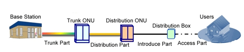
Fiber-to-the-home FTTH fiber cable laying usually divided into a trunk section. A distribution section, an introduction section, and an access section from the base station to the user.
As shown in Figure 1.
Generally, if there are fewer fiber optic cable segments generated from the fiber optic cable link, the fiber optic cable link system will be safer.
So why is the FTTH cable route divided into so many cable segments?
01
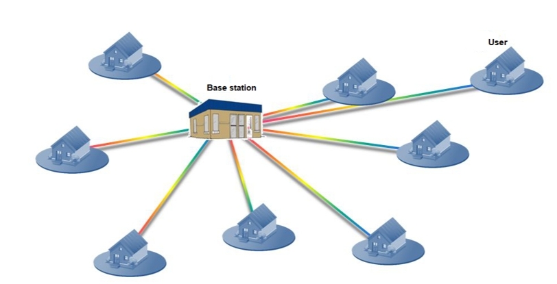
If the fiber optic link from the base station to the user only passes through one fiber optic cable segment (excluding jump fiber). That is, each user has a cable that goes directly to the board, as shown in Figure 2. What’s the problem?
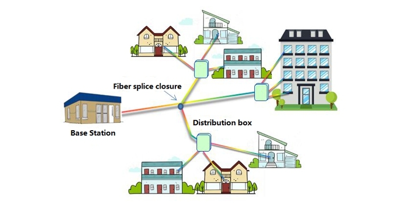
In order to solve the above problems, we have made 2 improvements, FTTH fiber cable laying as shown in Figure 3:
(1) The fiber optic cable separated from the large-core fiber optic cable. And then the fiber optic cable joint is closed to divide it into multiple small-core optical cables. It should be noted that if there are too many branch points on a fiber optic cable. It will affect the life and transmission indicators of the cable.
(2) The fiber optic distribution box set at the location where the users are concentrated as a branch point between the project and the load. When the user places the equipment, only a small cable needs to placed from the fiber optic distribution box to the user.
It is estimated that an office has 10 optical cables. Each optical cable has 6 to 12 optical fiber distribution boxes. And each optical fiber distribution box has 8 users. The number of service users in an office is 480 to 960. At this time, the optical cable line from the office to the user has become two cable segments: base station-distribution box, distribution box-user. Since the connection relationship of the optical fiber fixed at the closure of the optical cable joint and the attenuation is small. The closure of the optical cable joint is generally not used as the starting point of the segmentation.
Improved FTTH Wiring
Compared with Figure 1, the number of service users in the office in Figure 2 has increased several times. But the capacity is still too small. In addition, the development of users is dynamic. If a certain location needs to add a fiber optic distribution box. It is necessary to re-lay the fiber optic cable from the base station.
As can be seen from the comparison of Figure 2. 3 and Figure 3. As shown in Figure 2, from the perspective of reducing the number of outgoing optical cables and facilitating loading. The capacity of the station can be increased by adding branch points on the optical cable. There are two types of optical cable branch points: optical cable distribution box and optical fiber splice closure.
Through optical cable distribution, one optical cable can be divided into multiple optical cables. And the number of different branches is mainly limited by the conditions of optical cable laying. The connection relationship between optical cables is flexible. But this will increase the loss of active connections and make core management more difficult.
The number of cables that can be branched through fiber spice closure is small. Generally not more than 6 (1 to 5). Cables are usually left on both sides of the fiber optic splice closure. If there are more cables in the splice closure box, the cables will appear messy and ugly. Therefore, usually, the number of fiber optic joints closed to divergent fiber optic cables is controlled within 4 (1 to 3).
By increasing the optical cable distribution box as shown in Figure 5. The number of service users in the 480 distribution box is 960, the number of service users in one distribution box is 8 to 12, and 6 to 12 fiber optic feeders are placed in each optical fiber cable.
How many optical cable branches can be set up in a base station?
So how many optical cable branches can be set up in a base station? There are 10 optical cables in a base station. Each optical cable has 3 optical connections, and 30 optical connections can be set up. In this way, the capacity of the base station is about 14400-28800; such a large capacity can basically meet the needs of a large number of sites.
The construction of the project will be limited by the construction conditions. For example, if the optical cable network is to cover the residential area, it is preferred to set up optical communication in the residential area. However, when building a backbone optical cable base station, most residential properties will not allow construction in their communities. When the market department and a community negotiate the conditions for the construction of the project, the backbone optical cable project has been completed.
The engineering construction demand of urban cluster markets such as residential areas and commercial buildings is uncertain, and the construction of trunk optical cables must be completed within a certain period of time (generally within 2 to 3 months). In order to solve this contradiction, in the construction of backbone optical cables, the trunk ONU is placed close to the potential user group to facilitate the laying of cables, as well as installation conditions.
When construction conditions exist in residential areas, commercial buildings and other cluster markets, the distribution ONU is installed, and the optical cable is wired from the trunk ONU to the distribution ONU, as shown in Figure 6. Therefore, the optical cable line from the base station to the user is divided into the following parts: trunk section, wiring section, introduction section and home section.