Shanghai Gengyun Industrial Co., Ltd
Long Distance Loose Tube OPGW Cable 24 Core Optical Power Ground Wire Optical Fiber Cable
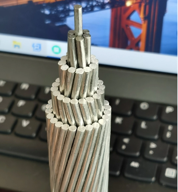
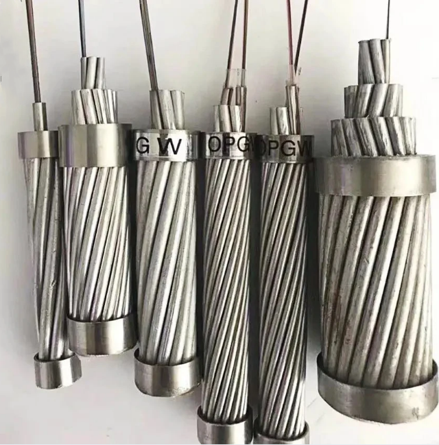
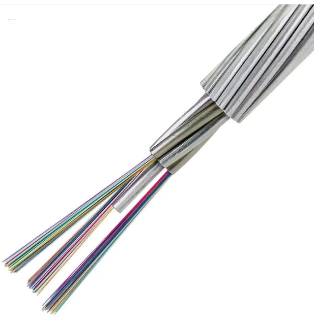
OPGW optical cable combines optical fiber and copper wire (or other metal wire) together. It can transmit both optical signals and power. OPGW optical cable is suitable for long-distance communication transmission occasions. OPGW optical cable has low fiber transmission loss, which can ensure the stability and reliability of communication signals during long-distance transmission.
The No.T-FC052 fiber optic composite overhead ground wire (OPGW) is a type of overhead ground wire containing optical fibers, which has multiple functions such as overhead ground wire and optical communication. Optical power ground wire is mainly used for communication lines in 110kV, 220kV, 500kV, 750kV, and new overhead high-voltage transmission systems. It can also be used to replace the existing ground wire of old overhead high-voltage transmission systems, add optical communication lines, conduct short-circuit currents, and provide lightning protection. Special structures can be customized according to user needs.
Product Feature
1.Stainless steel tube protects optical fibers with high tensile strength;
2.Small optical fiber composite cable diameter, light weight, and low additional load on the tower;
3.The optical unit forms a suitable excess length of primary optical fiber;
4.Slightly poor performance in terms of tensile resistance, torque resistance, and lateral pressure resistance;
Product Application
1. Communication lines in high-voltage transmission systems;
2. As an overhead ground wire, OPGW has all the functions of a traditional ground wire, including lightning protection, short-circuit current transmission, and mechanical support for the line. It can provide the necessary grounding protection for power lines and ensure the safe and stable operation of the power system.
Technology Parameters
| Attenuation | Tape Width | Polarization mode dispersion(PMD) | |||||||||
| @850nm | @1300nm | @1310nm | @1550nm | @850nm | @1300nm | Single Fiber | Link capacity(M=20,Q=0.01%) | ||||
| G652D | — | — | ≤0.35dB/km | ≤0.21dB/km | — | — | ≤0.20ps/km | ≤0.1ps/km | |||
| G655 | — | — | — | ≤0.22dB/km | — | — | ≤0.20ps/km | ≤0.1ps/km | |||
| 50/125μm | ≤3.0dB/km | ≤1.0dB/km | — | — | ≥600MHz.km | ≥1200MHz.km | — | — | |||
| 62.5/125μm | ≤3.5dB/km | ≤1.0dB/km | — | — | ≥200MHz.km | ≥600MHz.km | — | — | |||
| Type | Material | Value | |||||||||
| Structure | Fiber Optic | G652D/G655,etc | 2~48 cores | ||||||||
| Protective tube | Stainless steel pipe | 1.5~6mm | |||||||||
| Twisted single wire | Aluminum clad steel/aluminum alloy/aluminum rod | 1.5~6mm | |||||||||
| Maximum diameter | 18mm | ||||||||||
| Maximum cross-sectional area | 200mm2 | ||||||||||
| Mechanical Performance | Meet Standard DL/T832-2016 | ||||||||||
| Maximum tensile force(RTS)(kN) | 280 | ||||||||||
| Maximum flattening force(N/100mm) | 2200 | ||||||||||
| Maximum short-circuit current capacity(40ºC~200ºC)(kA2s) | 100 | ||||||||||
| Minimum bending radius(dynamic) | 20D | ||||||||||
| Minimum bending radius(static) | 15D | ||||||||||
| Environmental Performance | Installation temperature range (ºC) | -10~+50 | |||||||||
| Operating and storage temperature range(ºC) | -40~+65 | ||||||||||
Other fiber cores, fiber types, and strand types can all be designed.
| Attenuation | Tape Width | Polarization mode dispersion(PMD) | |||||||||
| @850nm | @1300nm | @1310nm | @1550nm | @850nm | @1300nm | Single Fiber | Link capacity(M=20,Q=0.01%) | ||||
| G652D | — | — | ≤0.35dB/km | ≤0.21dB/km | — | — | ≤0.20ps/km | ≤0.1ps/km | |||
| G655 | — | — | — | ≤0.22dB/km | — | — | ≤0.20ps/km | ≤0.1ps/km | |||
| 50/125μm | ≤3.0dB/km | ≤1.0dB/km | — | — | ≥600MHz.km | ≥1200MHz.km | — | — | |||
| 62.5/125μm | ≤3.5dB/km | ≤1.0dB/km | — | — | ≥200MHz.km | ≥600MHz.km | — | — | |||
| Type | Material | Value | |||||||||
| Structure | Fiber Optic | G652D/G655,etc | 2~48 cores | ||||||||
| Protective tube | Stainless steel pipe | 1.5~6mm | |||||||||
| Twisted single wire | Aluminum clad steel/aluminum alloy/aluminum rod | 1.5~6mm | |||||||||
| Maximum diameter | 18mm | ||||||||||
| Maximum cross-sectional area | 200mm2 | ||||||||||
| Mechanical Performance | Meet Standard DL/T832-2016 | ||||||||||
| Maximum tensile force(RTS)(kN) | 280 | ||||||||||
| Maximum flattening force(N/100mm) | 2200 | ||||||||||
| Maximum short-circuit current capacity(40ºC~200ºC)(kA2s) | 100 | ||||||||||
| Minimum bending radius(dynamic) | 20D | ||||||||||
| Minimum bending radius(static) | 15D | ||||||||||
| Environmental Performance | Installation temperature range (ºC) | -10~+50 | |||||||||
| Operating and storage temperature range(ºC) | -40~+65 | ||||||||||
| NO. | Technical Parameter | ||||||||||
| Model | Fiber optic cable structure form | Maximum number of optical fibers (core) | Aluminum clad steel section | Outer diameter | Mass per unit length(kg/km) | Rated breaking force(kN) | 20 ºC DC resistance | Allow short-circuit current capacity | |||
| (mm2) | (Q/km) | (40-200ºCkA2.s) | |||||||||
| (mm) | |||||||||||
| 1 | T-FC052 | 6/3.0/20AS,optical unit | 24 | ≈40 | 9 | ≤304 | ≥51 | ≤2.10 | ≥9 | ||
| 1/3.0 | |||||||||||
| 2 | T-FC053 | 6/3.2/20AS,optical unit | 24 | ≈50 | 9.6 | ≤345 | ≥58 | ≤1.82 | ≥11.5 | ||
| 1/3.2 | |||||||||||
| 3 | T-FC054 | 6/3.8/20AS,optical unit | 48 | ≈70 | 11.4 | ≤475 | ≥77 | ≤1.30 | ≥24 | ||
| 1/3.8 | |||||||||||
| 4 | T-FC055 | 6/3.8/40AS,optical unit | 48 | ≈70 | 11.4 | ≤340 | ≥42 | ≤0.70 | ≥38 | ||
| 1/3.8 | |||||||||||
| Other fiber cores, fiber types, and strand types can all be designed. | |||||||||||
Environmental Performance
| Mechanical and environmental performance testing | ||||||||||
| Item | Testing Method | Acceptance criteria | ||||||||
| Pull | GB/T7424.2-E1 | 40% RTS fiber has no significant strain (0.01%), and the fiber has no significant additional attenuation (0.03dB). | ||||||||
| Load: Based on changes in fiber optic cable structure | 60% RTS fiber strain ≤ 0.25%, fiber additional attenuation ≤ 0.05dB (after tension cancellation, there is no significant residual additional attenuation of the fiber (0.03dB) | |||||||||
| Sample length: not less than 10m; | ||||||||||
| Link not less than 100m | ||||||||||
| Duration: 1 minute | ||||||||||
| Flattening | GB/T7424.2-E3 | After the experiment, the additional attenuation of single-mode fiber at 1550nm wavelength should not exceed 0.05dB/fiber, and there should be no mechanical damage to the OPGW. | ||||||||
| Load: According to the above table, | ||||||||||
| Test 3 points for a duration of 10 minutes | ||||||||||
| Seepage water | GB/T7424.2-F5 | No water seepage | ||||||||
| Time: 1 hour | ||||||||||
| Sample length: 0.5m Water height: 1m | ||||||||||
| Temperature cycling | GB/T7424.2-F1 | After experiment,the additional attenuation of single-mode fiber at 1550nm wavelength should not exceed 0.1dB. | ||||||||
| Sample length: not less than 500m | ||||||||||
| Temperature range: -40 ºC~+70 ºC | ||||||||||
| Number of cycles: 2 | ||||||||||
| Insulation time: not less than 12 hours | ||||||||||
| Packaging |
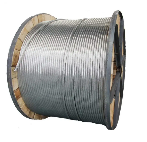
| Standard disc tools |
