
Shanghai Gengyun Industrial Co., Ltd
FC/UPC Single-Fiber Patch Cords
FC/UPC Single-Fiber Patch Cords
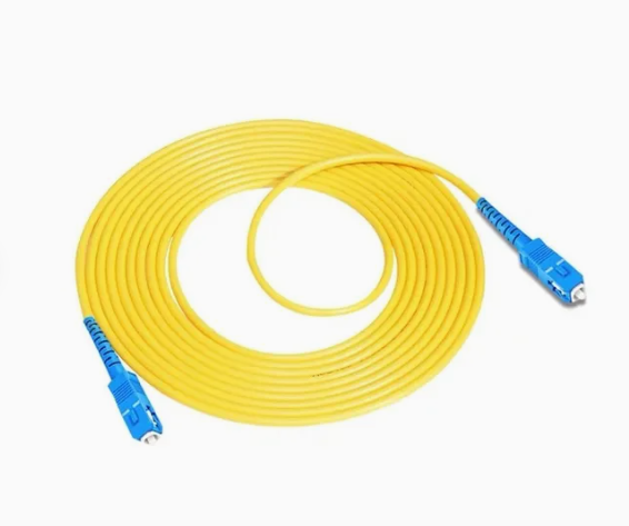
The FC/UPC single-core optical fiber patch cord is a fundamental building block of fiber optic connectivity. It consists of a single fiber terminated with FC connectors featuring Ultra Physical Contact (UPC) polish on both ends. The FC connector offers threaded coupling for a secure mechanical connection, while the UPC polish ensures excellent return loss performance for most digital applications. This single-fiber configuration suits applications requiring independent fiber paths or where duplex assemblies are impractical, serving as a workhorse for flexible connections and equipment interconnections in fiber networks.
Connector Configuration
Each end of the patch cord features a complete FC connector assembly including the 2.5mm ceramic ferrule, precision metal barrel, and threaded coupling nut. The connectors undergo rigorous inspection to verify geometric parameters ensuring low insertion loss. UPC polish on both ends provides return loss typically exceeding 50dB, suitable for all but the most demanding analog applications. Color coding typically uses blue or black strain relief boots to indicate UPC polish.
- Fiber Types Available
FC/UPC patch cords accommodate various fiber types matched to application requirements. Single-mode versions use 9/125μm fiber for long-distance and high-bandwidth applications. Multimode versions use 50/125μm or 62.5/125μm fiber for short-reach connections. Bend-insensitive G.657 fibers may be specified for applications requiring tight routing. The choice depends on the network equipment and distance requirements.
- Cable Construction
The fiber within the patch cord receives protection through multiple layers. A primary coating of 250μm surrounds the glass fiber. A tight buffer of 900μm may be applied for additional protection in rugged applications. Strength members of aramid yarn provide tensile reinforcement. The outer jacket, typically PVC or LSZH material, provides environmental protection and flame resistance appropriate for the installation environment.
- Performance Grades
Manufacturers offer various performance grades to match application requirements and budget. Standard grade patch cords suit general-purpose use with insertion loss below 0.3dB. Premium grade cords offer loss below 0.15dB for critical paths. Each connector undergoes individual testing with results provided for quality verification. All grades meet or exceed relevant industry standards for mechanical durability and environmental performance.
Key Applications and Use Cases
FC/UPC single-fiber patch cords serve diverse applications across telecommunications, data networking, and test environments. Their secure connection and excellent optical performance make them suitable for demanding applications.
- Equipment-to-Patch Panel Connections
In central offices and data centers, FC/UPC patch cords connect equipment ports to patch panels. This arrangement provides flexibility for future changes while protecting expensive equipment connectors from frequent handling. The FC connector ensures connections remain secure despite cable movement during maintenance activities. Single-fiber configuration allows independent routing of individual fibers.
- Test Equipment Interfacing
Test laboratories extensively use FC/UPC patch cords to connect instruments to devices under test. The secure threaded coupling ensures consistent measurements without risk of accidental disconnection. The UPC polish provides stable return loss essential for accurate measurements. Multiple cord lengths accommodate various test setups, from benchtop connections to remote test points.
- Cross-Connect Applications
Cross-connect fields use single-fiber patch cords to create temporary or semi-permanent connections between network elements. The FC connector’s threaded coupling prevents accidental disconnection that could disrupt service. Individual fibers can be patched independently, providing maximum flexibility for network reconfiguration. Color-coded boots aid in organization and troubleshooting.
- Laboratory and Research Applications
Research environments require reliable, repeatable connections for experimental setups. FC/UPC patch cords provide the stability needed for sensitive measurements. The single-fiber configuration allows precise control of optical paths. Various fiber types accommodate different wavelengths and experimental requirements. The robust construction withstands frequent reconfiguration common in research settings.
Performance Characteristics and Specifications
Understanding patch cord specifications ensures proper selection for specific applications. Manufacturers provide detailed performance data to guide purchasing decisions.
- Optical Performance
Insertion loss represents the most critical optical parameter for patch cords. Quality FC/UPC single-fiber patch cords achieve insertion loss below 0.3dB per connector pair, with premium grades below 0.15dB. Return loss typically exceeds 50dB for UPC polish, ensuring minimal reflections that could affect laser stability. These values remain stable over temperature and after multiple mating cycles.
- Mechanical Durability
FC/UPC patch cords undergo testing to verify mechanical robustness. Connectors typically withstand 500-1000 mating cycles without significant performance degradation. Cable strain relief protects the fiber-cable junction from breakage during handling. Tensile load testing verifies that strength members effectively protect the fiber during installation. Flex testing ensures durability during repeated bending.
- Environmental Specifications
Patch cords must operate reliably across installation environments. Temperature range typically spans -40°C to +75°C for indoor applications. Outdoor-rated versions extend this range and add UV resistance. Damp heat testing verifies performance in humid environments. Flame retardance ratings match installation requirements, with riser, plenum, and LSZH options available.
- Length Accuracy
Precision length measurement ensures patch cords meet ordered specifications. Typical length tolerance is +0/-0.5 meters for standard cords, with tighter tolerances available for critical applications. Length markings on the cable aid in identification and inventory management. Custom lengths accommodate specific installation requirements without excess slack.
Selection and Handling Guidelines
Proper selection and handling maximize patch cord performance and service life. Following established practices prevents damage and ensures reliable operation.
- Length Determination
Select patch cord length appropriate for the application without excessive slack. Measure the actual path including vertical rises and horizontal runs. Allow some slack for service loops but avoid coils that could cause magnetic field interactions. Consider future reconfiguration needs when selecting length. Custom lengths optimize installations where standard lengths prove inadequate.
- Polarity Considerations
For single-fiber applications, polarity is straightforward as each cord connects a single transmit or receive path. However, maintain consistency in connector orientation to simplify troubleshooting. Document connections clearly to aid future maintenance. When using multiple single-fiber cords for duplex links, ensure proper pairing of transmit and receive paths.
- Bend Radius Management
Even with bend-insensitive fiber options, maintain recommended minimum bend radius during installation and operation. Typical recommendation is 10x cable diameter under load, 15x for long-term installation. Avoid tight bends at connector strain relief boots. Use cable managers and guides to maintain proper radius. Excessive bending increases loss and may cause permanent fiber damage.
- Cleaning and Inspection
Clean patch cord connectors before every connection using appropriate tools. Inspect with a fiberscope to verify cleanliness and detect damage. Never touch ferrule end faces with bare fingers. Install dust caps immediately after disconnection to protect from contamination. Regular cleaning and inspection prevent performance degradation and intermittent problems.
FAQs
1. What is the difference between FC/UPC and FC/APC patch cords?
The difference lies in the connector polish. FC/UPC patch cords feature Ultra Physical Contact polish with a slightly curved ferrule end face, providing return loss above 50dB, suitable for most digital applications. FC/APC patch cords use Angled Physical Contact with an 8-degree polish, achieving return loss above 65dB for analog video and high-speed DWDM systems. UPC connectors typically use blue or black boots, while APC uses green. Never mix different polish types, as the geometry mismatch creates an air gap that destroys performance.
2. How do I select the correct length for an FC/UPC patch cord?
Measure the actual path the cord will follow, including vertical runs, horizontal distances, and service loops. Add approximately 10% for routing flexibility. Standard lengths include 1m, 2m, 3m, 5m, and 10m, with custom lengths available. Avoid excessive slack that requires coiling, as coils can cause magnetic field interactions and complicate cable management. For rack installations, measure from port to port accounting for vertical cable managers and horizontal routing.
3. Can I use FC/UPC single-fiber patch cords for duplex applications?
Yes, you can use two single-fiber FC/UPC patch cords for duplex applications requiring separate transmit and receive fibers. Simply designate one cord for transmit and one for receive, maintaining consistent orientation. Some installers use different colored boots or labels to distinguish the two paths. For applications with many duplex connections, consider using duplex patch cords with two fibers joined together for simpler cable management and polarity consistency.
4. How often should I clean FC/UPC patch cord connectors?
Clean FC/UPC patch cord connectors before every connection. Even a tiny dust particle can cause significant loss or damage polished end faces. Use appropriate cleaning tools such as reel-based cleaners or cassette cleaners designed for fiber connectors. Inspect with a fiberscope after cleaning to verify results. Install dust caps immediately after disconnection to protect from contamination. Regular cleaning prevents performance degradation and extends connector life.
Company Introduction: With over 20 years of deep industry expertise, we specialize in customizing and supplying solutions for optical fibers, cables, raw materials, and manufacturing equipment. We deliver reliable technical support and product services.
About the Author: With 20 years of hands-on experience in optical transmission media, cable assemblies, and core substrate materials, we offer practical, expert insights grounded in full-industry-chain expertise.