
Shanghai Gengyun Industrial Co., Ltd
Hollow-Core Photonic Crystal Fiber
Manufacturing Process Overview Producing hollow-core photonic crystal fiber requires specialized fabrication techniques. The stack-and-draw method remains the industry standard for this complex structure. Manufacturers assemble hundreds of glass capillaries into precise geometric arrangements. This assembly then undergoes controlled drawing into kilometer-length fiber lengths. Each process step demands exceptional precision to preserve the delicate air-hole structure. Manufacturers start […]
Manufacturing Process Overview
Producing hollow-core photonic crystal fiber requires specialized fabrication techniques. The stack-and-draw method remains the industry standard for this complex structure. Manufacturers assemble hundreds of glass capillaries into precise geometric arrangements. This assembly then undergoes controlled drawing into kilometer-length fiber lengths. Each process step demands exceptional precision to preserve the delicate air-hole structure.
- Capillary Preparation Methods
Manufacturers start by producing uniform glass capillaries with tight tolerances. Outer diameter consistency must stay within 0.1mm for successful stacking. Wall thickness variations cause hole size irregularities in the final fiber. Advanced drawing towers produce capillaries with exceptional geometric uniformity. Capillary quality directly determines the final fiber’s optical performance.
- Stacking Pattern Design
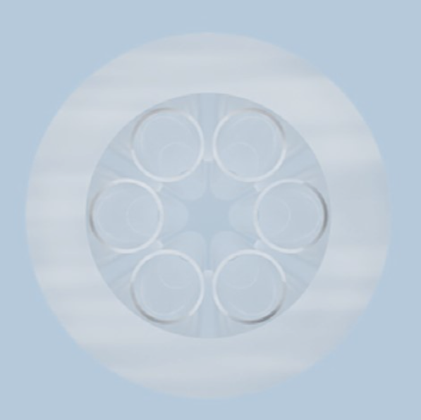
The capillary arrangement defines the fiber’s photonic bandgap properties. Hexagonal close-packed patterns offer the most efficient structure. Missing or misplaced capillaries create defect states that degrade guidance. Computer-controlled stacking rigs ensure accurate pattern replication. Pattern precision requires sub-millimeter positioning accuracy across hundreds of capillaries.
Critical Process Control Parameters
Several variables determine whether the fiber structure survives drawing. Each parameter requires tight control throughout production.
- Temperature Profile Management
The drawing furnace temperature must remain within a narrow window. Too hot and the capillary structure collapses before drawing. Too cold and the glass becomes too viscous for consistent drawing. Temperature variations of just 10°C can destroy the air-hole pattern. Thermal control represents the single most critical process parameter.
- Pressure Control During Drawing
Applying differential pressure preserves the air-hole structure during drawing. The central hole and surrounding capillaries receive pressurized gas. This pressure counteracts surface tension that would collapse the structure. Pressure must be adjusted dynamically as fiber diameter changes. Pressure management requires sophisticated feedback control systems.
Structural Quality Inspection
Verifying the internal structure requires specialized measurement techniques. Quality control must detect defects before fiber reaches customers.
- Microscopic Cross-Section Analysis
Periodic sampling verifies the air-hole structure along the fiber length. High-resolution microscopy captures the full cross-sectional geometry. Automated image analysis measures hole diameters and wall thicknesses. Any pattern distortion triggers process adjustments or rejection. Structural inspection confirms the fiber meets design specifications.
- Optical Guidance Verification
Optical testing confirms the fiber guides light at target wavelengths. Bandgap position and width are measured spectroscopically. Transmission loss testing verifies attenuation meets specifications. Any deviation from expected guidance indicates structural defects. Optical qualification provides final acceptance criteria for production fiber.
Yield Improvement Strategies
Manufacturers continuously work to improve production yields. Several approaches address common failure modes.
- Defect Source Analysis
Tracking defect types identifies the most frequent failure causes. Capillary variations often cause localized pattern distortions. Pressure fluctuations create periodic diameter variations along the fiber. Temperature instability leads to collapse in specific furnace zones. Root cause analysis guides process improvement investments.
- Process Automation Benefits
Automated stacking systems reduce human error in preform assembly. Closed-loop pressure control maintains structure during drawing. Machine vision inspects fiber continuously for diameter variations. Automation reduces yield variability between production runs. Process automation enables consistent high-quality production at scale.
FAQs
1. What is the typical yield for hollow-core photonic crystal fiber production?
Commercial yields range from 30-60% for production runs. Research production may see lower yields of 10-20%. Yield improves significantly with process maturity and automation. The complex structure makes 100% yield unlikely. Manufacturers factor yield losses into production costing.
2. How long does it take to produce one kilometer of hollow-core fiber?
Drawing speed is much slower than standard fiber at 1-5 meters per minute. Standard fiber draws at 1000-2000 meters per minute. A single kilometer requires 3-15 hours of drawing time. The slow speed reflects the delicate structure preservation requirements. Production costs are significantly higher than standard fiber.
3. Can the air-hole pattern be repaired if damaged?
Pattern damage cannot be repaired once the fiber is drawn. The only solution is rejecting the affected fiber length. Preform assembly errors also cannot be fixed after stacking. Prevention through careful process control is the only strategy. This is why yield improvement remains a major focus.
Company Introduction: With over 20 years of deep industry expertise, we specialize in customizing and supplying solutions for optical fibers, cables, raw materials, and manufacturing equipment. We deliver reliable technical support and product services.
About the Author: With 20 years of hands-on experience in optical transmission media, cable assemblies, and core substrate materials, we offer practical, expert insights grounded in full-industry-chain expertise.