
Shanghai Gengyun Industrial Co., Ltd
Single mode Pigtail Type Fiber Optic PLC Splitter Module
PLC Splitter Modules
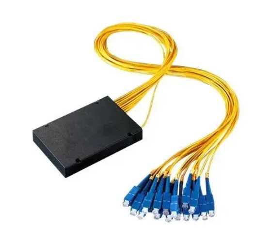
The singlemode pigtail type fiber optic PLC splitter module divides one optical signal into multiple outputs. PLC stands for planar lightwave circuit, a chip-based splitting technology. This module includes factory-attached pigtail fibers for easy field connection. Singlemode operation supports standard telecom and FTTH wavelengths. Network operators use these splitters for passive optical network deployment.
- PLC Technology Overview
Planar lightwave circuits are manufactured on silica or polymer substrates. Photolithography creates waveguide patterns that split light evenly. The chip design determines the split ratio from 1×2 to 1×64. PLC splitters offer excellent uniformity across all output ports. This technology has largely replaced fused biconical taper splitters.
- Pigtail Configuration Benefits
Factory-attached pigtails eliminate field splicing for splitter connection. Pigtails are color-coded for easy port identification. Input pigtail typically uses a different color than outputs. The module housing protects the delicate PLC chip and fiber junctions. Installation requires only connecting pigtail connectors to patch panels.
Key Applications and Use Cases
PLC splitters are fundamental to passive optical networks. Each application uses specific split ratios and form factors.
- Fiber to the Home Distribution
FTTH networks use splitters to serve multiple homes from one fiber. A 1×32 splitter at a distribution point feeds 32 homes. The splitter module installs in outdoor cabinets or manholes. Pigtail connections simplify deployment in the field. This architecture reduces central office equipment requirements significantly.
- Optical Distribution Networks
Enterprise and campus networks use splitters for efficient fiber utilization. A 1×8 splitter feeds eight offices from one backbone fiber. Splitters can be cascaded for larger distribution ratios. The passive nature requires no power or cooling at distribution points. This simplicity reduces operational expenses.
Performance Specifications
Several parameters define PLC splitter quality. Understanding these helps network engineers select appropriate modules.
- Insertion Loss and Uniformity
A 1×8 splitter typically has 10.5 dB maximum insertion loss. A 1×32 splitter reaches 17 dB typical loss. Uniformity measures the loss variation between output ports. Quality splitters maintain uniformity within 1-1.5 dB. Excess loss accounts for energy not reaching output ports.
- Wavelength Dependence
PLC splitters operate across 1260-1650nm wavelength range. Loss variation with wavelength is typically under 1 dB. This wide range supports CWDM and DWDM applications. Return loss exceeds 50 dB for single-mode splitters. Polarization-dependent loss stays below 0.3 dB.
Installation Guidelines
Proper handling ensures splitter module reliability. Following these guidelines prevents performance degradation.
- Bend Radius Management
Pigtail fibers require minimum bend radius protection. A 30mm radius is typically recommended for single-mode fibers. Sharp bends increase loss and can permanently damage fibers. Use cable management guides with adequate radius. Secure pigtails without compressing or kinking the fibers.
- Connector Cleaning and Mating
Clean all connector end faces before mating to splitter pigtails. Use appropriate dry cleaning tools for connector type. Inspect connectors with a fiberscope before connection. Mate connectors fully until a click is heard. Properly mated connectors show no gap between end faces.
FAQs
1. What is the maximum split ratio available for PLC splitters?
Standard PLC splitters go up to 1×64 ratio. Larger ratios like 1×128 are possible but rare. Higher split ratios have higher insertion loss. A 1×64 splitter typically has 20-21 dB loss. For larger splits, cascading smaller splitters is often preferred.
2. Can PLC splitters be used in reverse direction (combining)?
Yes, PLC splitters are passive and work bidirectionally. Multiple signals can combine into a single fiber. This application is called a coupler or combiner. However, combining efficiency equals the splitting ratio. A 1×8 splitter used as a combiner has 9 dB loss.
3. How does temperature affect PLC splitter performance?
PLC splitters operate normally from -40°C to +85°C. Loss variation with temperature is typically under 0.5 dB. The module housing protects the chip from thermal stress. Outdoor installations should use environmentally sealed enclosures. Industrial temperature range versions are available for extreme environments.
Company Introduction: With over 20 years of deep industry expertise, we specialize in customizing and supplying solutions for optical fibers, cables, raw materials, and manufacturing equipment. We deliver reliable technical support and product services.
About the Author: With 20 years of hands-on experience in optical transmission media, cable assemblies, and core substrate materials, we offer practical, expert insights grounded in full-industry-chain expertise.